
近年、多種多様な製品の生産後の膨大な製品種のアフターサービスの維持において3Dプリンター技術(Additive Manufacturing; 積層造形技術;付加造形とも。以下、AM)は、小・中量生産、スペアパーツや補修機能において重要な役割を果たしています。また金属AMは、リードタイムの削減だけではなく、コストの削減や部品のデジタル化、サプライチェーン維持の補助を実現します。例えば、破損した金属部品を取り換える場合は、設計図や金型を起こすところから始める必要がありますが、スキャニング技術とAMの特徴を活用することで品質を維持したまま欠損部分のみを肉盛りと機械加工によって再生することができます。そのためには、金属AMにおける代表的な設計プロセスを理解しておくことが必要です。
1. はじめに
近年、多種多様な製品の生産後のアフターサービスの維持においてAMは、小・中量生産、スペアパーツや補修機能において重要な役割を果たしています。AMは、リードタイムの削減だけではなく、コストの削減や部品のデジタル化、サプライチェーン維持の補助を実現します。例えば、インフラ産業の例を挙げると、古いプラント等で金属部品が破損し、部品製造元の会社が存在しておらず、部品供給に支障が発生した場合があるとします。この際は別の製造会社を探すなり、最悪、設計図や金型を起こすところから始める必要があり、大きな作業コストが発生します。但し、スキャニング技術とAMの特徴を活用することで品質を維持したまま欠損部分のみを肉盛りと機械加工によって再生し、コスト発生を回避することができます。
本稿では、スキャニング技術と金属AMにより、インフラ産業や他産業等で使用される金属部品(以下、本製品)が破損したケースを想定した場合の補修プロセス(設計、製造プロセス)について解説をしています。本稿には、あるインフラ装置で使用される部品が破損した場合を想定して、金属AMで補修できるようになるまでのプロセスについて説明します。その後、試験片と仮定の部品(部品A)を作成し、試験片においては試験機を活用した引張試験を実施して、単一材料と複数材料(肉盛り材料)の定量的な比較評価までを行います。タービンブレードを活用するインフラ産業や他産業等の実務について言及しません。
留意点:本稿は「インフラ産業や他産業等」で利用されている「タービンブレード」をAMとスキャニング技術を活用した場合を想定し、株式会社3D Printing Corporationが作成したレポートです.あくまで仮定ベースのプロセスの解説であり、実部品等の造形・耐久実験等は行っておりません。


Table 1 前提条件
2. 【AMプロセス】 前提条件
金属部品が破損した状況を仮定して、金属3Dプリンターを修理や補修手段として活用した場合の製造プロセスに関して説明します。前提条件はTable1の通りです。
また、本稿ではDED(Direct Energy Deposition)方式の一つであるワイヤーDED方式を採用した金属3DプリンターであるMeltio450を活用します。金属3Dプリンターの主流は金属粉末材料ですが、本機は金属ワイヤーを活用します。金属ワイヤーの3Dプリンターには大まかにDED方式とWAAM方式があります。金属ワイヤー方式を活用する理由とDED方式である本機を活用する理由は以下の通りです。
WAAM方式でなくDED方式を活用する理由は、入熱量です。WAAM方式では破損した金属部品等の修理・補修を金属3Dプリンターで行う場合は、入熱量が多いため、熱変形を考慮する必要があります。なぜなら、大きな入熱量は部品の熱変形を起こし、パフォーマンスに悪影響を及ぼすからです。(※入熱量による修理・補修の対象となる金属部品の熱変形等の解析・分析については、また別のコラムで紹介します)
金属ワイヤーを活用する理由は、オペレーションが簡単で運用コストが低い、また安価だからです。金属粉末を活用した金属3Dプリンターは精度の高い製品をサポート材が少ないあるいは使用せずに造形できます。ただ、金属粉末を活用した金属3Dプリンターは付帯設備導入等のコストが大きく、粉末状の材料である性質上、粉塵爆発等の危険性が高く、オペレーションが複雑で運用が難しいという傾向があります。また、そのため一品当たりの造形コストが高くなります。また、造形やメンテナンスの維持に多大なケアが必要になります。
上記の理由から、金属部品のパフォーマンス向上のためにはワイヤーDED方式を採用したMeltio450が有効であると判断しました。
3. 【AMプロセス】 破損部品を削って土台作り
本稿のMeltio450は3軸の3Dプリンターなので、Z軸方向にしか成膜することができません。ゆえに、3軸の3Dプリンターを利用して肉盛りする場合、まずは破損品を地面から水平に切削し、造形部分をFig. 1の右側ように3Dプリンターの仕様で造形できるように本製品の破損部分を整える(≒切削して)必要があります。これをすることで、Z軸方向に成膜するための平らな土台が施された残存部分(以下、母材)が完成します。

Fig 2:左)破損部分の切削前 右)破損部分の切削後

Fig 3:部品Aを削っている様子
4. 【AMプロセス】欠損部分の3Dスキャン(Fig. 4の②)
「3」にて破損部分と母材の間にある破損によって生じた凸凹を平らにしました。ですが、このままでは3Dプリンターで欠損部分の肉盛りをすることができません。3DプリンターはFig. 4のような手順を踏んでようやくプリントをすることができます。
3Dプリンターはデータを起点とします。今回の母材のように、既に存在する物体の上に3Dプリンターにプリント指示を出すためには、物質世界の物体の寸法に限りなく近く、正確なデジタルデータを作成する必要があります。これを「ネットシェイプ(Net Shape)[1]」といいます。そのような正確なデジタルデータを作成するには、一次的に3Dスキャン技術のように物質世界のものをデジタルに変換する技術を活用します。そのための手順がFig. 4です。
オペレーターが3Dスキャナーを活用し、物質世界にある物体の表面情報(点群データ)を収集して、荒い3D(メッシュ)データを作成します。
[1] Net Shape: 正味の、掛け値なしの最終形状
① 母材の切削(必要であれば)
↓
② スキャニング
↓
③ 3Dデザイン作成・調整
↓
④ スライス(層生成)
↓
⑤ プリント
↓
⑥ 後処理加工(切削等)完成
Fig 4:「3Dデータ」から「完成」までの手順
5. 【3Dデータの補正と作成(Fig. 4の③)】データの補正
「4」で物質世界の情報をデジタルデータに変換しました。デジタルデータの正確性は、その3Dスキャナーの仕様と性能、測定を実施する環境に依存し、現在ではかなり完成度の高いデジタルデータを最初の測定で作成することができます。しかし、メッシュデータは3Dプリンターで使用するには精度が不足しています。そこで、メッシュデータをより高次元なデータ(以下、3DCADデータ等)に変換する必要があります。現状ではその不足をソフトウェアによる自動生成機能による補助や人間(エンジニア等)の手で補っています。


6. 【3Dデータの補正と作成(Fig. 4の③)】データの作成
母材の3DCADデータが完成したので、修理・補修用データ(以下、肉盛りデータ)の作成を始めることができます。今回は「5」で作成した3DCADデータを基礎に、本製品欠損部分の再設計をします。ここで、再設計の際に念頭に置かなければならない前提が切削加工の工程です。
切削を前提に考えた場合、欠損部分と同じ体積のみを肉盛りしてしまっては切削後の完成品がネットシェイプより小さくなってしまいます。これを防ぐためには、破損部分に余肉(あまじし)を付与する必要があります(Fig. 8参照)。このように完成品に限りなく近い形状を「ニアネットシェイプ(Near-Net Shape)[2]」といいます。
[2] Near-Net Shape: 最終形状に近い形状


7. 欠損部分の肉盛り(Fig. 4の④⑤)
再設計データを活用して、金属3Dプリンターでの修理・補修を始めることが可能になります。母材の上にワイヤーを成膜していく方法は従来のミグ溶接等の溶接技術とほとんど同じですが、こと金属3Dプリンターでは工作機械である性質上「基準点」の定義が大事になってきます。基準点がずれると結果的に母材と再設計データにずれが発生し、正常に成膜することができなくなります。基準点は3軸金属3Dプリンターのほかにも、ロボットやポジショナーを活用した5軸・6軸の金属3Dプリンターも存在します。
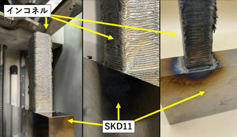
基準点を合わせて、プリントが完了した試験片がFig. 10/Fig. 11/Fig. 12のようになります。母材の上に余肉が付与された欠損部分が肉盛りされたニアネットシェイプを再現することを想定した造形ができました。


8. 【後処理加工(Fig. 4の⑥)】切削加工
本稿含め、金属3Dプリンターでの修理・補修だけでは、高精度の寸法公差を達成することは不可能です。必ず切削加工等の機械加工を工程に含める必要があります。
ニアネットシェイプから余肉部分を切削機械で寸法公差を達成した本製品(≒ネットシェイプ)に削り出していきます(Fig. 13)。本稿では切削加工は実施していません。

9. 【後処理加工(Fig. 4の⑥)】試験片のプレートからの切り外し(EDM)
切削加工が終了した後にプレートから製品を取り外す必要がある場合は、EDM(加工放電)等を活用して切り離しを行います(Fig. 13を参照)。

10. 引張試験
Fig. 10/Fig. 11で作成した造形物をFig. 13であるようにEDMでカットし、「SKD11(試験片A群)」と「SKD11+Nickel718(試験片B群)」を3個ずつ作成しました(Fig. 14/Fig. 15/Fig. 16)。本稿の試験片は熱処理をおこなっておりません。Fig. 15を見てもわかるように、肉盛りが開始する部分の接合断面を目視で確認する限りは、外観はきれいに融合されていることがわかります。


作成した試験片A群・B群を社内の精密万能試験機を活用して引張試験を実施しました(Fig. 17)。結果はFig. 18の通りです。B群がA群に比べてわずかに強度が低く、接合部で破断したことにより変位量がA群の半分になりました。強度としては両郡とも同等の強度であるといってもいい結果が出たと考えています。造形したNickel718の試験片を作成した後に引張試験を実施することも検討しています。


11. おわりに
本稿では、スキャニング技術と金属AMにより、インフラ産業や他産業等で使用される金属部品が破損したケースを想定した場合の補修プロセス(設計、製造プロセス)について解説をしてきました。また、作成した試験片(熱処理未実施)の引張試験を実施して、母材と肉盛りされた母材の引張強度を導き出すことができました。
解説とともに、実際に試験片を通して欠損部分のみを肉盛りと機械加工によって再生するプロセスを実演しました。試験片の引張試験では、一材料と複数材料(肉盛り材料)の定量的な比較評価によって、一材料と複数材料とで同等の引張強度の結果を得ることができました。
今後は熱処理をかけた試験片を作成し、引張試験の実施や仮定で造形した部品の切削加工等の実施をする予定です。
--
Meltio詳細情報:こちら
わたしたち3D Printing Corporationは、日本市場におけるMeltio社の金属3Dプリンターの販売を行っています。
また同プリンターを使用し造形サービスも行っております。
弊社工場見学にて、実際に実機をご覧になることも可能ですので、ご興味のある方はお気軽にご相談ください。
メール経由:info@3dpc.co.jp へ「Meltioに関する問い合わせ」等の旨をご記入の上、お問い合せください。