近年、エンジンを中心とした自動車生産量が減少する中、3Dプリンター技術(Additive Manufacturing;積層造形技術;付加造形とも。以下、AM)は試作、小・中量生産、補修機能において重要な役割を果たしています。また金属AMは、リードタイムの削減だけでなく、性能の向上を実現します。例えば、設計の柔軟性において、より優れた熱適合性を見つけ出すことで、耐疲労性の向上や品質の安定を図ることができます。そのためには、金属AMにおける代表的な設計プロセスを理解しておくことが必要です。
1. はじめに
近年、エンジンを中心とした自動車生産量が減少する中、AMは試作、小・中量生産、補修機能において重要な役割を果たしています。AMの使用は、リードタイムの削減だけでなく、性能の向上を実現します。例えば、設計の柔軟性において、より優れた熱適合性を見つけ出すことで、耐疲労性の向上や品質の安定を図ることができます。
本稿では、設計により自動車部品に活用されるダイキャスト金型の冷却性能向上と実製作に金属AMを活用した際の設計、製造プロセスについて解説をしています。具体的には、ある自動車部品のダイキャスト金型を想定して、直線型チャネルと形状適応型チャネルの2種類のチャネルを施した金型データを設計します。その後、CAEソフトウェアで2種類の金型の冷却性能を数値解析した後、比較評価までを行い、形状適応チャネルを施した金型のAM製作を前提とした設計プロセスと活用価値についての解説をしています。自動車業界の実務について言及しません。
※留意点:本稿は「自動車産業」で利用されている「ダイキャスト」製法をAMとCAE(Computer Aided Engineering)を活用した場合を想定し、株式会社3D Printing Corporationが作成したレポートです。あくまで、仮定ベースのアプリケーションを想定試験であり、実際にダイキャストでは実験を行っておりません。
2. 【設計プロセス】 金型の冷却について
前提として鋳造工程における金型の冷却性能は、生産品の品質、生産性、金型寿命に大きな影響を与えます。したがって、最適な冷却性能を有した金型の設計および製造が肝要になります。主にダイキャスト用の金型にも同じことが言えます。
金型の冷却チャネルはStraightDrilled Cooling Channel(直線型冷却チャネル)が主流です。StraightDrilled Coolingとは、切削技術を用いて金型に定規で引いたような直線状のチャネルをキャビティの周りに通しているものをいいます。単純な形状の切削加工であるために、金型の生産者にとって加工が容易であり、円滑に冷却を行うことができます。しかし、Straight Drilled Cooling金型はキャビティ形状によって冷却性能が制限されるため、不均一な冷却になる可能性があります。そこで、キャビティの形状に関係なく均一な冷却性能を有するチャネルの設計および開発が必要になってきます。
これらの点を解決するためにConformal[1]Cooling Channel(形状適応型冷却チャネル)の研究が盛んに進んでいます。キャビティの形状に沿って冷却チャネルを設計するConformal CoolingはStraight Drilled Coolingとは異なり、キャビティの形状に沿って等間隔で冷却チャネルを設計することができ、キャビティ全体を均一に冷却することができます。しかし、Conformal Coolingが適応された金型内部は形状が複雑になるため、一般的な機械切削加工(以下、CNC)による製作が不可能で実用化できず、ほとんどは設計とコンピュータシミュレーション分析にとどまっています。
そこで製作の困難を克服するために「引き算」の切削加工法ではなく、製作する形状の制約が少ないうえに、設計自由度の高い「足し算」のAM技術が着目されています。
[1] Conformalとは「形状適応」という意味合いがあります。
3. 【設計プロセス】 デザインプロセス

2で説明した内容を前提に、それぞれStraight Drilled CoolingとConformal Coolingの金型データを作成します。まずは自動車部品のダイキャスト金型(凹凸)のデザインを作成します。次にTable 1の条件でそれぞれStraight Drilled CoolingとConformal Coolingのチャネルを施したデザインを二つ作成します。これでFig1のようなデータができます。Conformal Cooling金型は一般的なAM方式であるPowder Bed Fusion(粉末床溶融結合法。以下、PBF)方式の金属3Dプリンター(以下、金属3DP)を活用した製作を前提にしています。AMは製作する形状の制約が少ないため、切削加工を想定した直線型チャネル設計にこだわる必要がなく、高い設計自由度の形状(この場合はチャネル)を製作前提で設計することが可能になります。

また、ConformalCooling金型のチャネルデザインはFig 2のように真円ではなくティアドロップ型に変更しています。デザインのチャネル断面が真円だと積層が上部に差し掛かるにつれて非常に急なオーバーハングとブリッジを形成して断面が重力の方向に潰れていきます。こうなると製作が失敗する原因にもなりますので、フィージビリティ[2]と造形成功率を上昇させるためにはAMに適したティアドロップ型が最適解になるわけです。このようにAMに適した(再)設計をDfAM(Design for Additive Manufacturing)と言います。
[2] Feasibilityとは実現可能性の意味合いがあります。

4.【シミュレーション】AMとシミュレーション
CAEがAMにおいて便利なツールとなる理由に「1. AMプロセスの最適化」と「2. ラピッドプロトタイピング([ラピッド]=迅速な、[プロトタイピング]=試作モデルの開発)」が挙げられます。
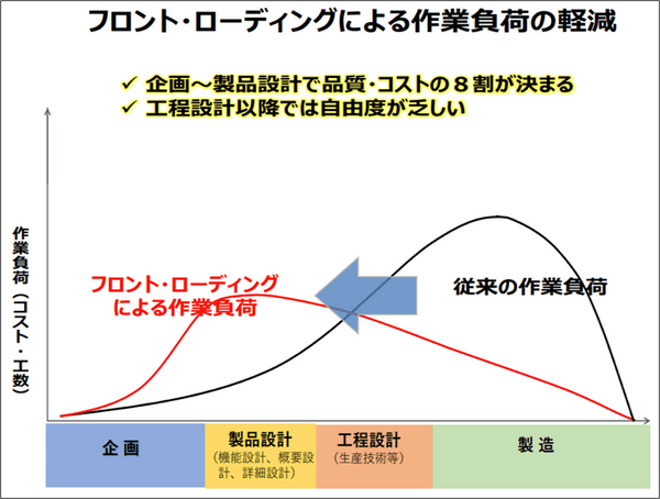
Conformal Cooling金型を製作するPBF方式金属3DPにはデメリットがあります。その一つは高いランニングコストです。具体的には金属粉末材、大量の不活性ガス、大規模な付帯設備、粉塵被曝・爆発の可能性を加味したPPEの装備や取り扱いが必要等です。これらの要素が1回毎の造形コストを圧迫します。CAEを活用すれば、造形するモデルの解析と評価のイタレーション[3]をデジタル上で繰り返すことができ、高コストな造形の必要回数を最小限に抑えることができます。結果として、1を達成でき、PBFの経済的な活用が可能になります。これは設計のデジタル化に伴い、フロント・ローディングによる作業負荷の軽減を達成することになります(作業荷量:企画>製品設計>工程設計>製造)。
[3] IIterationとは一連の工程を短期間で繰り返す開発サイクルのこと。

また、企業は製品開発において、試作品の製造・評価段階に莫大な時間をかけています。CAEを活用することで、試作品の①企画、②設計、③製造、④解析、⑤評価、⑥実地検証、⑦再設計、⑧生産の大部分をシミュレーションソフトウェア(数値)上の仮説設定で完結させ、アジャイル開発により製品のTime-to-Marketの時間短縮を実現することが可能になります。例えば、④・⑥以外はCAE上で完結することが可能です。CAEを活用することで企業は製品開発において大幅な時間短縮と、節約された時間を活用してより多くの試作品候補のラピッドプロトタイピングによるイタレーションを繰り返すことが可能になります。
5.【シミュレーション】CAEを活用したシミュレーション
CAEソフトウェア(Ansys Fluent[4])を活用して、設計した金型データにアルミニウムを圧入した時のキャビティ表面の平均温度値の推移をデジタル上で解析することができます。今回の結果はFig 5 - 8のように視覚的に見ることができます。
[4] Ansys FluentはAnsys社の登録商標です。


6.【シミュレーション】結果と考察
シミュレーションで得られた結果を、Table 2にまとめています。Conformal Cooling金型は、Straight Drilled Coolingと比較して冷却性能が3%ほど上昇し、平均冷却温度が向上する解析結果が得られました。また、Fig 6とFig 8のコンター図で確認できるように、Conformal Coolingを活用した金型がStraight DrilledCoolingを活用した金型に比べて均一に内部にかけて冷却されていくことも判明しました。

7. AM造形プロセス
AMではどの方式でもデータが起点になります。今回作成した金型データを製作する際はまずスライスを行います。スライスとは、データを必要に応じてz軸向きに幾層にも分割することです。このスライスデータは金属プリンター付属のソフトウェアで作成できることがほとんどです。スライスデータを入力後、準備ができたらプリントを実行できます。造形する形状によって、最適なパラメータを設定・開発する必要があり、限りなく完成品に近い形を造形します(これをニアネットシェイプといいます)。すべての層を成膜できた時点で造形は完了です。
ここで完成したニアネットシェイプの造形品を金型として活用できるようにするには、CNCとのハイブリッド加工によって寸法公差を整えることが必須になります。無事切削加工が終われば製作品の完成です。
8. おわりに
本稿では、設計によるStraight Drilled CoolingとConformal Coolingの2つの金型データの冷却性能をCAEシミュレーションで比較評価して、定量的に得られることを解説しました。また、その金型データを金属3Dプリンターで製作する際のプロセスについて解説しました。
本稿では金型の冷却効率向上をAMとCAEを交互に活用することで、AM製作前提の高い設計自由度でConformal Coolingのような従来の切削加工法では製作できなかった複雑な形状を応用し、複数のデザイン候補をデジタル上で同時に数値解析と比較評価(ラピッドプロトタイピング)することによって最適なデザインを開発することによって実施することができます。
今後は、実際に設計したConformal Cooling金型データを金属プリンターでプリントして実製作する予定です。また、今回は切削間加工までの製造プロセスについて説明をしましたが、切削加工の他にも残留応力除去のための処理が必要なケースもあります。その際はHIP処理などの工程追加等を慎重に検討する必要があります。
【引用文献】
経済産業省製造産業局、 (2022年9月8日)。
第8回 産業構造審議会 製造産業分科会。
参照日: 2022年12月
参照先: 経済産業省 Ministry of Economy, Trade and Industry: https://www.meti.go.jp/shingikai/sankoshin/seizo_sangyo/pdf/008_02_00.pdf